Dashboard
Overall Idea
The design of the Vehicle Dashboard UI utilizes the Qt framework, with components arranged using either QML language or Qt Designer. The UI is organized into five main tabs, each serving a distinct purpose:
Tabs in the Dashboard
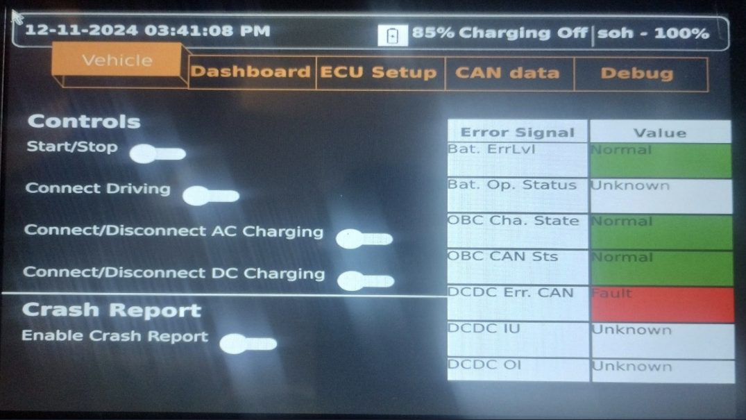
- Vehicle: This tab includes controls and monitoring related to the vehicle's operation, such as battery startup, charging status, and fault notifications.
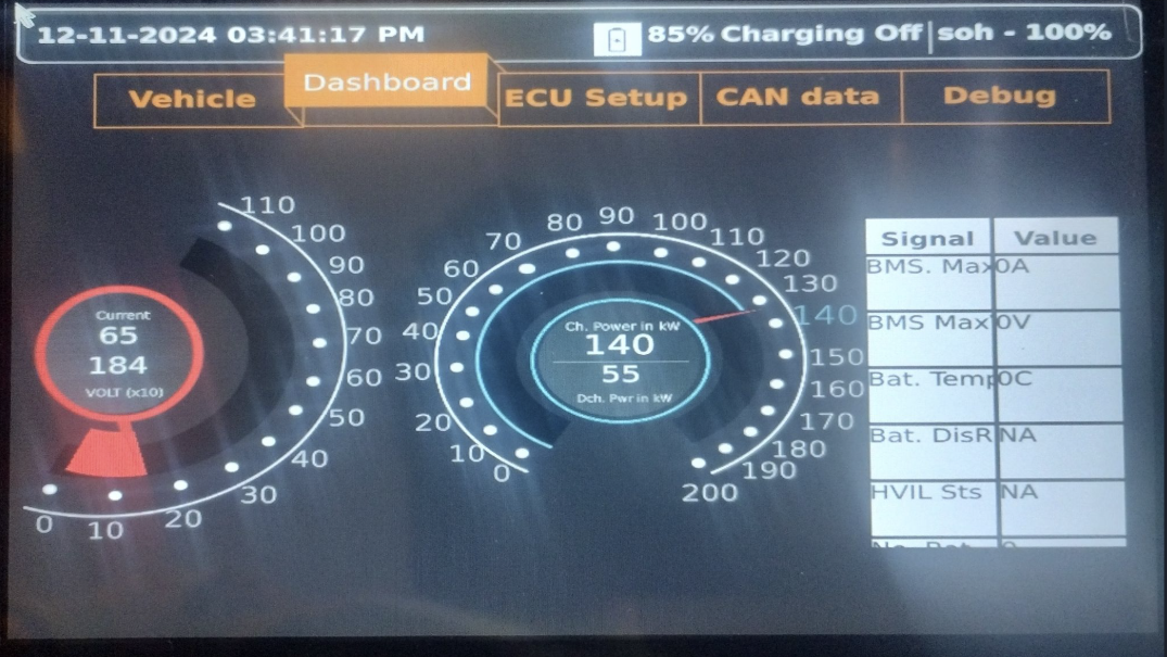
- Dashboard: This tab displays essential real-time data and statistics, including vehicle speed, battery health, and other critical vehicle parameters.
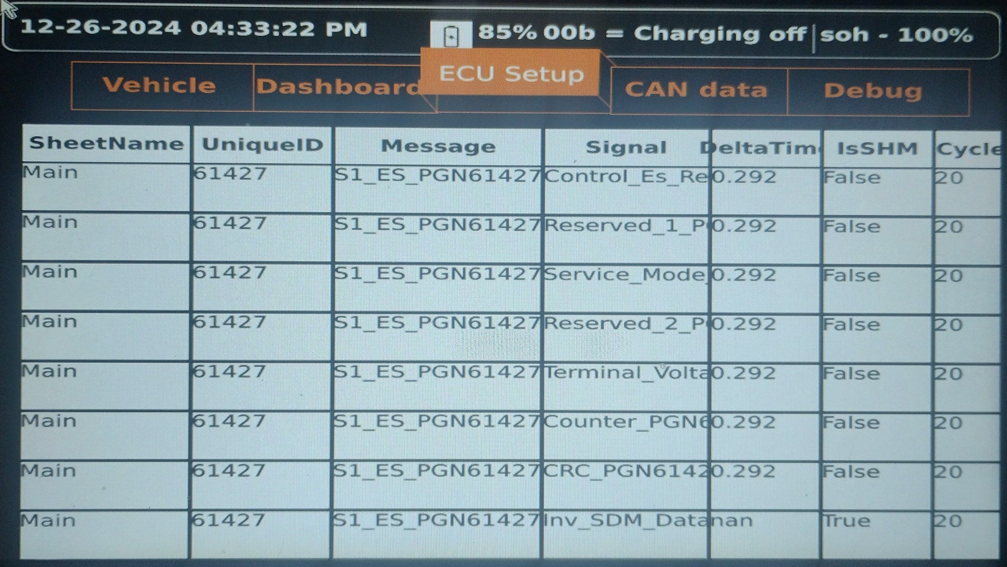
- ECU Setup: This tab allows the user to configure and monitor the vehicle's Electronic Control Units (ECUs). It provides interfaces for ECU communication and configuration.
- CAN Data: This tab shows the raw CAN data being transmitted and received across the vehicle's CAN network. It allows for monitoring and debugging of CAN signals.
- Debug: This tab provides debugging tools and logs for troubleshooting issues within the system. It includes error messages, logs, and other diagnostic tools to ensure the system is functioning properly.
Hardware-in-the-Loop (HIL)
What is Hardware-in-the-Loop (HIL)?
Hardware-in-the-Loop (HIL) is a testing methodology where real hardware components (e.g., ECUs, sensors, actuators) are integrated with a simulated environment to validate the functionality of the system. It bridges the gap between simulation and real-world deployment.
Why is HIL Required?
HIL testing is essential because:
- Realistic Validation: It allows testing of the Vehicle Control Unit (VCU) and other components in a controlled environment that mimics real-world conditions.
- Risk Reduction: Identifies and resolves issues before deploying the system in an actual vehicle, reducing the risk of failures.
- Cost Efficiency: Reduces the need for expensive physical prototypes and field testing.
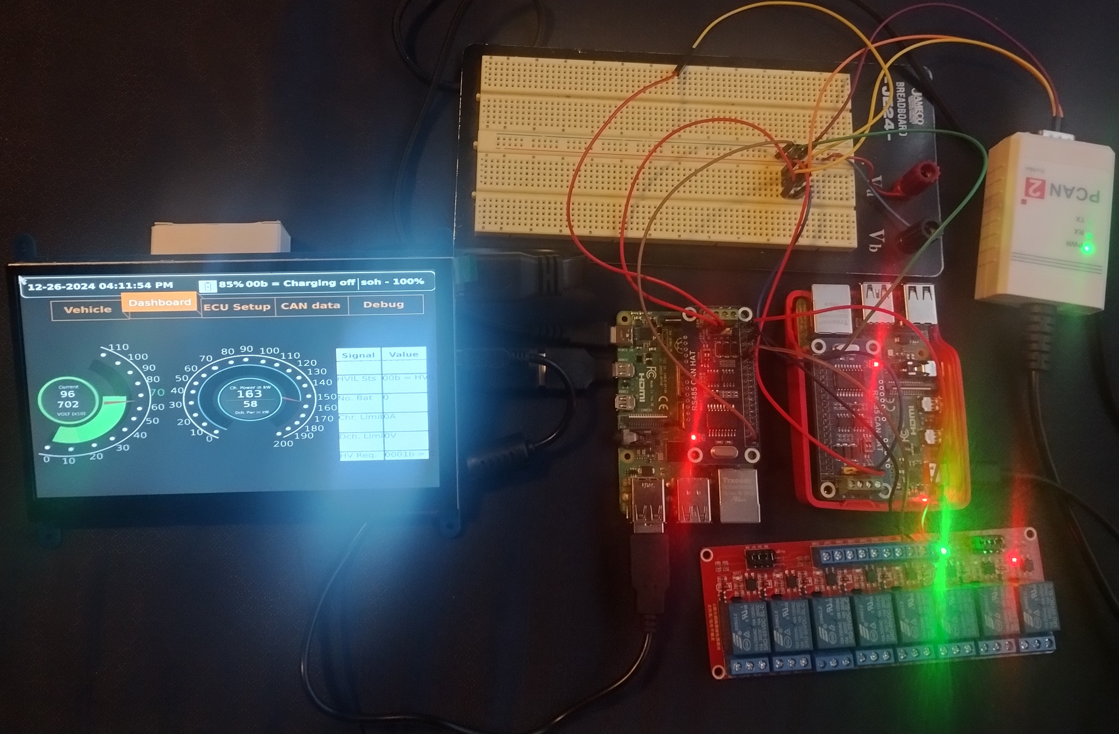
HIL Setup in This Framework
The HIL setup consists of:
- Two Raspberry Pi 4 (RPi 4) devices communicating over a CAN Bus operating at 500 kbps.
- A laptop connected to the CAN network to sniff and monitor CAN data.
Roles of the Components:
a. RPi 1 (VCU):
Acts as the Vehicle Control Unit, sending required messages for:
- Turning on the battery
- Initiating driving or charging modes
b. RPi 2 (Battery ECU):
Simulates the Battery Management System (BMS), responding to VCU messages with:
- Battery status
- Safety checks
- Fault notifications
c. Laptop:
Monitors and logs CAN data for debugging and validation.
Key Steps in HIL Testing
a. Safety Messages:
The VCU sends a set of safety messages following J1939-76 rules to ensure proper communication with the Battery ECU.
b. Dashboard Integration:
A Qt-based dashboard is used to control and monitor the system, providing an intuitive interface for:
- Turning on/off the battery
- Monitoring CAN signals
- Debugging issues
Actual Component Test
In this phase, the framework is tested with real hardware components (e.g., actual Battery ECU, VCU, and other ECUs) to validate its functionality in a real-world environment. This step ensures that the system performs as expected under actual operating conditions.
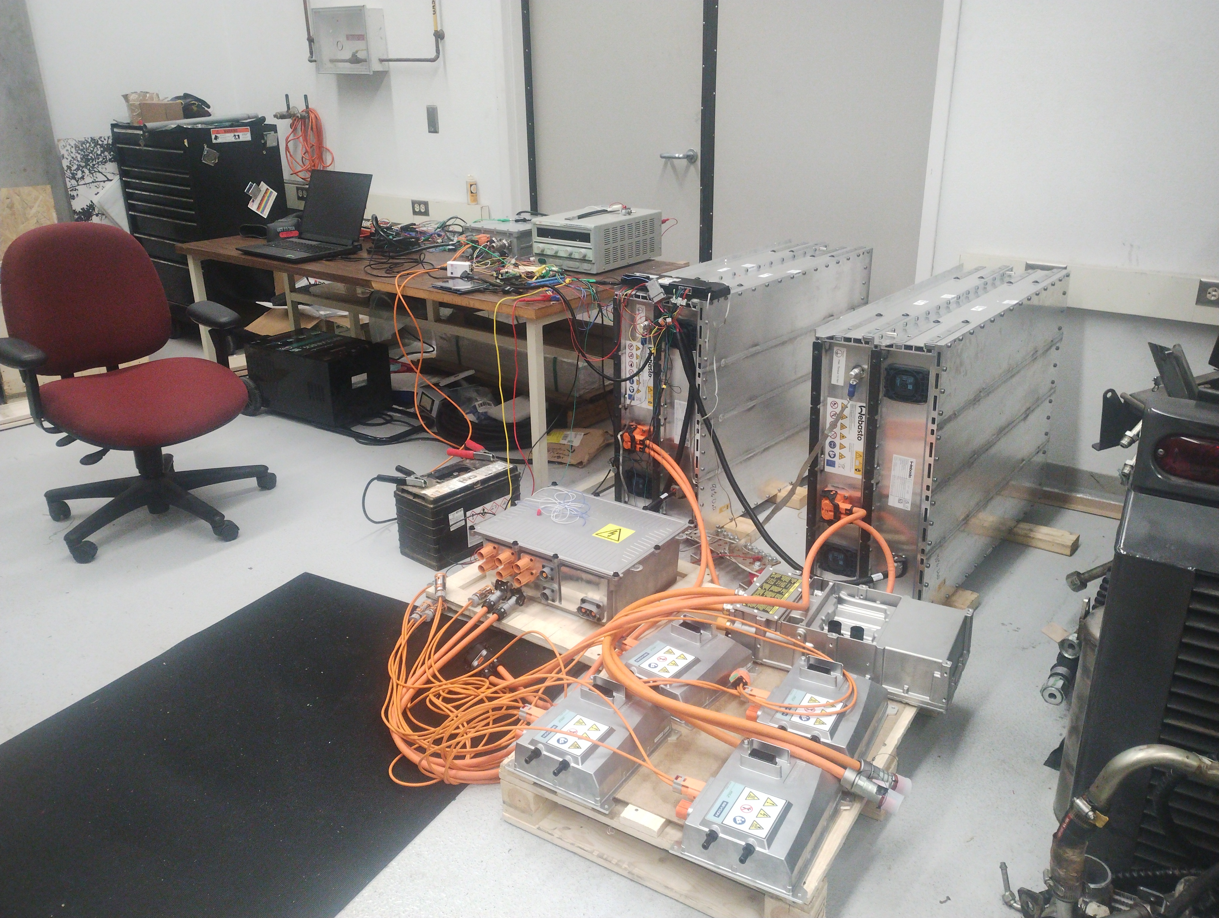
System Overview
- Batteries: Two 400V batteries connected in series to provide 800V.
- Vehicle Interface Gateway (VIG): Reads data from both batteries and forwards it on the Vehicle CAN bus at a current of 130A.
- Power Distribution Unit (PDU): Manages power distribution across the vehicle.
- On-Board Charger (OBC): Regulates the charging process.
- Editron Inverter: Controls the motor.
- Vehicle CAN Bus: All components are connected to the Vehicle CAN bus, operating at 500 kbps.
- RPi as VCU: Our framework uses a Raspberry Pi (RPi) acting as the Vehicle Control Unit (VCU).
Steps to Set Up and Test the System
a. Understand the DBC for Each Component
- Each component requires specific CAN messages at particular intervals.
- Certain signals within these messages must have the correct values for proper communication.
- The ECU Setup screen in the framework handles this task. Messages and signal values added here are automatically encoded and sent by the framework.
- Decoded data is displayed in the CAN Data screen.
b. Interface One Node at a Time
- Initially, connect each component to a separate CAN bus. This is because the baud rate of each device may not be known beforehand.
- Use the configuration tool provided by each component to set the required parameters:
- PDU: Use CANamoon with CSV parameters.
- Editron Inverter: Use POWER User software.
- VIG: Use Webasto Peak config tool.
- Configure each component one at a time on a separate CAN bus. Use a DB9 connector with two terminal resistors and one node connected in between. Sniff the CAN data using a CAN analyzer tool to verify communication.
c. Integrate Components into the Vehicle CAN Bus
- Once each component is configured, integrate them into the Vehicle CAN bus.
- Ensure all components are communicating correctly and that the framework is sending and receiving the expected messages.
d. Validate Communication and Control
- Use the framework's dashboard to monitor and control the components.
- Verify that all devices are functioning as expected and that the system is stable under real-world operating conditions.
Summary
By following these steps, you can successfully set up and test the framework with real hardware components. The process involves:
- Understanding the DBC for each component.
- Configuring each component individually on a separate CAN bus.
- Integrating all components into the Vehicle CAN bus.
- Validating communication and control using the framework's dashboard.
Once the setup is complete, the system is ready for real-world operation, ensuring reliable communication and control across all components.
Key Points
- DBC Files: Ensure the DBC files for each component are correctly configured in the framework.
- Configuration Tools: Use the appropriate tools for each component to set the required parameters.
- Step-by-Step Integration: Test each component individually before integrating them into the Vehicle CAN bus.
- Validation: Use the dashboard to monitor and control the system, ensuring everything works as expected.
Features in UI and Code Connecting Them
Please understand the working of Qt-Creator and Qt-Designer before reading this section.
- Please note that all the subcomponent qml loads in the MainForm.ui.qml
- Feel free to use ChatGPT using these templates if you want to modify something on top of this. But be careful as GPT when I programmed was not trained on latest Qt version and most of the code it gives needs to modified. So, be carefull copying the code. It can even break the existing one.
- Each time the code in cpp or the qml is changed rebuild the project and hit on deploy
- The DashStack.qml is the front end code
- Dashboard.qml is only for the menu click
- Using this you can see important signals on dial as well as in the form of table specifically values but not the ecu status
- The ECUStack.qml is the front end code
- ECUSetup.qml is only for the menu click
- This is where the migrated messages or signals appear and user can double click on value or cycle to edit and remeber to restart the system to make this change reflect either through Debug tab or from Qt-Creator application
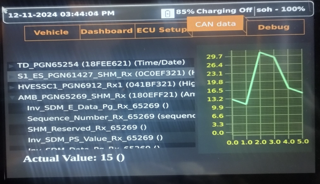
- The CANStack.qml is the front end code
- CANData.qml is only for the menu click
- This is where all the dbc tree is loaded and user can see any data decoded with description, trend over time etc
- The VehicleStack.qml is the front end code
- Vehicle.qml is only for the menu click
- Controls and table of faults status of the ecu's are shown here
Key Features:
a. Real-Time Monitoring:
- Displays live data from the vehicle's CAN network.
- Updates dynamically as new data is received.
b. Control Interface:
- Allows users to send commands to the VCU and other ECUs.
- Includes buttons for turning on/off the battery, starting/stopping charging, etc.
c. Debugging Tools:
- Provides logs and error messages for troubleshooting.
- Includes tools for analyzing CAN data and identifying issues.
Memory and Control Loop Logic
1 2 3 4 5 6 7 8 9 10 11 12 13 | |
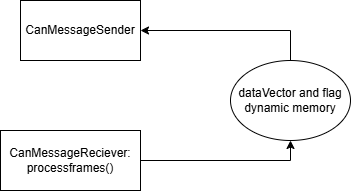
The above code basically lets you create a dyncamic memory which gets used in CanMessageSender Class Also, CanMessageReciever class processframes is where these values are set which is shown as below
1 2 3 4 5 6 7 8 9 10 11 12 13 14 15 16 17 18 19 20 21 | |
The above code decodes the current and voltage limit and sets it to respective datavector that we defined earlier. This happens only when dataVec[5] is zero which according dbc means connect for charging is pressed and battery is ready for charging
Memory Management
- The framework uses Qt's memory management to efficiently handle data and avoid memory leaks.
- Objects are managed using parent-child relationships, ensuring proper cleanup when no longer needed.
Control Loop Logic
- The control loop continuously monitors and processes CAN data.
- It uses Qt signals and slots to update the UI and trigger actions based on incoming data -- MainController class does this all the controls action or the function call happens here.
CAN Frame Logic
- CAN frames are decoded and processed based on the DBC file.
- The framework ensures that all CAN signals are correctly interpreted and displayed in the UI.
How to operate the Vehicle?
- Go here and understand the sequence of operation as in the CAN state diagram or the handshake between different nodes
- 'Enable Crash' is intentinally blocked from the UI. Enable it only when required or vehicle in operation
- All the CAN signals starts sending and responding happens when user toggles start/stop button
- When Connect for driving is toggled vehicle is ready for opeartion as in the power. Change the logic as describer previously if you need some messages to be sent on different button click based on the example
How to add new ecu details in ecu tab?
-
We do sql migration as the data in ecu tab is stored in sql database and on every boot this data will be populated automatically
-
main.cpp has code for migration -- remember if you acccidently insert or migrate the record multiple times. No worries! DBManager class has api to remove records
1 2 3 | |
- As shown above the migration is done for battery type component only. Becuase Battery has little different format of messgage encoding compared to other component
- CreateSHMData and CreateSDMData are the two functions used for encoding data in their respective format
- First column is SheetName which means this is used too differentiate Battery and other component
- Batteries has additional message named Safety Header Message (SHM) follows J1939-76
1 | |
- If sheet name is nonshm this corresponds to other than battery component
- Second column is a unique id usually keep pgn or some unique id. Keep the same id for each signal of message. So, it is unique to a message.
- You can edit any data from dashboard or from the code (this onvolves removing and inserting)
- Be sure to restart the app to make the changes