🚛 SAE J1939: The Standard for Heavy-Duty Vehicle Communication
SAE J1939 is a set of standards that define how Electronic Control Units (ECUs) communicate via the CAN bus in heavy-duty vehicles. It provides a common language for communication across ECUs, enabling interoperability across manufacturers. In contrast, cars often use proprietary OEM-specific protocols.
🔧 What is J1939?
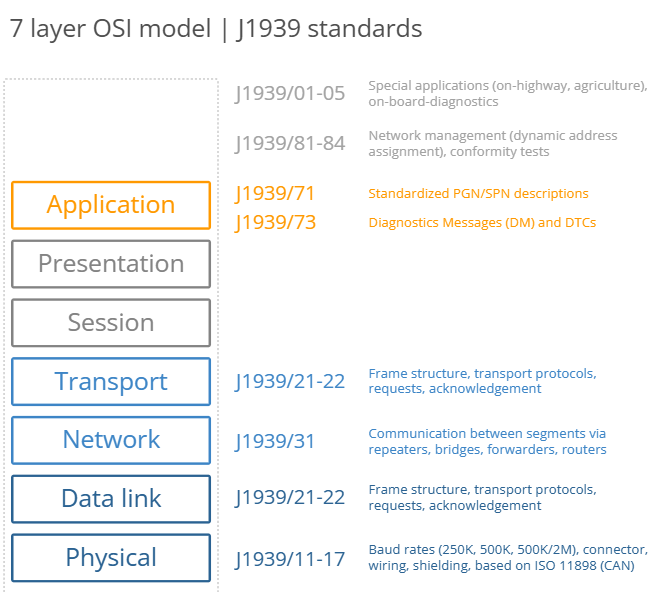
- J1939 is a higher-layer protocol based on CAN (Controller Area Network).
- CAN specifies the physical layer (ISO 11898-2) and data link layer (ISO 11898-1) of the OSI model.
- J1939 adds a standardized language for advanced communication, enabling ECUs to exchange data seamlessly.
Other CAN-based protocols include OBD2, UDS, and CANopen.
- To experiment with CAN specifically J1939 29bit ID and data and interested in encode and decode works please go to CAN Calculator
🛠️ Key Components of J1939
1. Parameter Group Number (PGN)
- The PGN is an 18-bit subset of the 29-bit extended CAN ID.
- It serves as the unique frame identifier within the J1939 standard.
- Multiple CAN messages with unique CAN IDs can map to the same PGN and be interpreted identically.
2. Suspect Parameter Number (SPN)
- The SPN identifies the CAN signals (parameters) in the data payload.
- SPNs are grouped by PGNs and described in terms of:
- Bit start position
- Bit length
- Scale
- Offset
- Unit
- This information is required to extract and scale SPN data into physical values.
🚚 Why J1939 Matters
- Standardization: J1939 provides a common language across manufacturers, enabling interoperability.
- Data Logging: The standardization is a key enabler for data logging use cases in heavy-duty vehicles.
- Efficiency: By defining a clear protocol, J1939 ensures efficient and reliable communication between ECUs.
🌐 J1939 vs. Proprietary Protocols
| Feature | J1939 | Proprietary Protocols |
|---|---|---|
| Interoperability | Standardized across manufacturers | Specific to OEMs |
| Use Case | Heavy-duty vehicles | Cars |
| Flexibility | Limited by standardization | Highly customizable |
🎯 Conclusion
SAE J1939 is the backbone of communication in heavy-duty vehicles, providing a standardized, efficient, and reliable method for ECUs to exchange data. By defining PGNs and SPNs, J1939 ensures that data is interpreted consistently across different systems and manufacturers.
✨ J1939 enables seamless communication, making it indispensable for modern heavy-duty vehicles!
More information can be found here.
Our Vehicle CAN Nodes
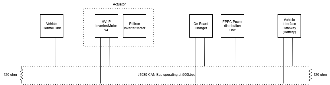
Need for Communication
In an electric vehicle (EV) architecture utilizing the J1939 CAN protocol, Electronic Control Units (ECUs) communicate continuously to ensure safe and efficient operation. The Vehicle Control Unit (VCU) acts as the central hub, facilitating seamless information flow between components.
🔄 Communication Between Components
🔋 Battery ECU (Vehicle Interface Gateway)
The Battery ECU monitors and safeguards the battery system.
📥 Inputs Required:
- Ambient temperature
- Vehicle speed
- Timestamp information
- High voltage control consent
- Isolation measurements
- Crash event data (frontal, side, etc.)
📤 Outputs Provided:
- State of Charge (SOC)
- State of Health (SOH)
- Voltage, current, and available energy metrics
🔌 On-Board Charger (OBC)
The OBC regulates the charging process based on the battery’s condition.
📥 Inputs Required:
- Maximum voltage and current limits (from BMS)
📤 Outputs Provided:
- Output voltage, current, and temperature status
- Operational status (e.g., readiness to charge or fault detection)
⚡ Power Distribution Unit (PDU)
The PDU manages high-voltage connections across the vehicle.
📥 Inputs Required:
- Instructions to close contactors for safe power distribution
📤 Outputs Provided:
- CAN communication faults
- Temperature readings
- DC voltage and current levels
- Internal faults and contactor status
🎛️ Editron Inverter
The Editron Inverter controls the motor.
📥 Inputs Required:
- Motor activation signals
- Control mode selection (speed, torque, or voltage control)
- Speed and torque limits
- Resolver feedback
📤 Outputs Provided:
- Motor speed and resolver status
- Fault codes
- DC link voltage readings
🚀 HVLP Inverters
The HVLP Inverters control four individual motors.
📥 Inputs Required:
- Battery demand current limits
- Torque requests from the VCU
📤 Outputs Provided:
- Measured speed, torque, and temperature data
- Fault diagnostics
- Encoder feedback
🎯 Conclusion
The seamless communication between these ECUs is fundamental to the electric vehicle’s safety, efficiency, and performance. The VCU plays a central role in orchestrating this communication, ensuring real-time data exchange for optimized energy use and system reliability. This integrated network enables responsive, safe, and reliable vehicle operation.
✨ Modern EVs rely on this robust communication architecture to deliver a smooth and efficient driving experience!
How to Use the Framework to Implement the Communication?
Follow these steps to implement communication using the framework:
-
Step 1: Learn about DBC
Understand the basics of DBC files and their role in CAN communication. -
Step 2: How to merge different components' DBC?
Learn how to combine DBC files from multiple components into a single file. -
Step 3: Make sure you have followed all RPi setup steps and know how to transfer the DBC to the root location
Set up your Raspberry Pi (RPi) and ensure the DBC file is correctly placed. -
Step 4: Migrate required data to the Grid or the ECU setup of the Dashboard
Transfer necessary data to the Grid or ECU setup for the dashboard. -
Step 5: How to launch the Dashboard from the laptop?
Learn how to start the Qt-based dashboard on your laptop. -
Step 6: How to operate the Dashboard?
Get familiar with the dashboard's features and how to use it effectively.